
TM 5-3805-261-23-2
FRAME SEPARATION AND CONNECTION REPLACEMENT
(CCE AND TYPE I MACHINES) - CONTINUED
0324 00
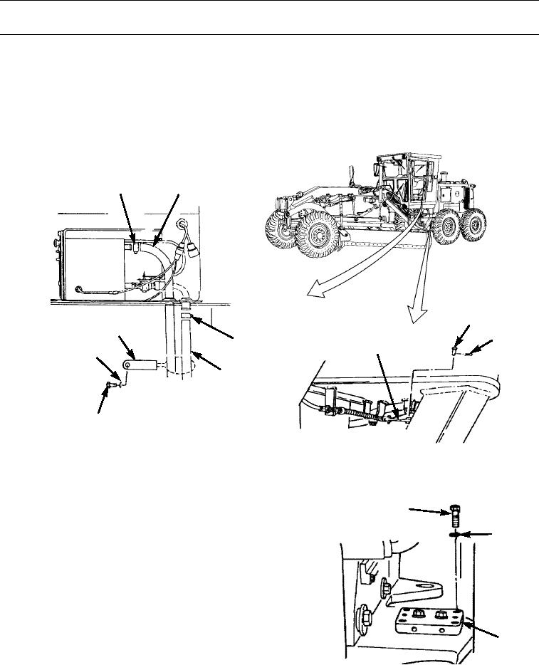
REMOVAL - CONTINUED
10.
Remove bolt (37), washer (38), and clip (39) (WP 0212 00).
11.
Remove clamp (32) and position heater hose (33) to rear of machine.
12.
Remove clamp (30) and position heater hose (31) to rear of machine.
13.
Remove cotter pin (35) and pin (34) from articulation indicator linkage (36). Discard cotter pin.
30
31
34
39
35
32
36
38
33
37
397-1943
14.
Position forklift at rear frame of machine.
15.
Position two jack stands under operator's platform on each side of machine.
16.
Position all wire, cable, and harness assemblies on
40
front of machine.
41
17.
Position all hose assemblies on rear of machine.
18.
Position wood blocks under front wheels so that
wheels cannot move.
19.
Remove four bolts (40) and lockwashers (41) from
four corners of plate (42). Discard lockwashers.
42
397-1944
0324 00-5