
TM 5-3805-261-23-2
FRAME SEPARATION AND CONNECTION REPLACEMENT
(CCE AND TYPE I MACHINES) - CONTINUED
0324 00
REMOVAL - CONTINUED
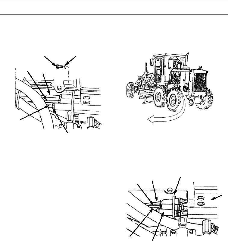
5.
Remove two bolts (21) and washers (22).
6.
Loosen three nuts (23) and slide back on control cable assemblies (24, 25, and 26).
22
21
25
26
24
23
397-1941
7.
Slide back retainer (27) and three couplings (29) on cable assemblies (24, 25, and 26).
NOTE
Tag wire, cable, and harness assemblies before disconnecting to aid in installation.
8.
Separate three cable assemblies (24, 25, and 26) from
27
26
transmission control valves (28) (WP 0152 00).
25
9.
Pull cable assemblies (24, 25, and 26) forward from
engine compartment and position cable assembly (26)
28
alongside left side of cab and cable assemblies (24 and
25) alongside right side of cab.
24
397-1942
29
0324 00-4