
TM 5-3805-261-23-2
SERVICE BRAKE AND WHEEL SPINDLE HOUSING ASSEMBLY REPLACEMENT - CONTINUED
0314 00
REMOVAL
NOTE
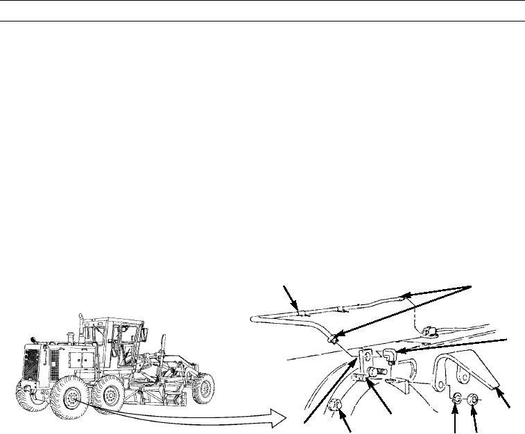
The following is a maintenance procedure for the right-rear brake and wheel spindle housing assembly. The
maintenance procedure for the remaining three brake and wheel spindle housing assemblies is identical.
1.
Remove two nuts (5), lockwashers (6), and guard (4) from brake and wheel spindle housing assembly (8). Discard lock-
washers.
CAUTION
Cap all hose and tube ends to prevent contamination.
NOTE
Tag hose and tube assemblies before removal to aid in installation.
2.
Loosen two nuts (2) on tube assembly (1).
3.
Remove tube assembly (1), elbow (3), bolt (7), and plate (9) from brake and wheel spindle housing assembly (8).
1
2
3
4
7
9
8
6
5
397-4254
0314 00-2