TM 5-3805-261-23-2
FINAL DRIVE ASSEMBLY REPLACEMENT - CONTINUED
0309 00
INSTALLATION - CONTINUED
WARNING
Use extreme caution when handling heavy parts. Provide adequate support and use assistance during proce-
dure. Ensure that any lifting device used is in good condition and of suitable load capacity. Keep clear of
heavy parts supported only by lifting device. Failure to follow this warning may cause injury or death to per-
sonnel.
NOTE
Final drive housing weighs 360 lb (163 kg).
15.
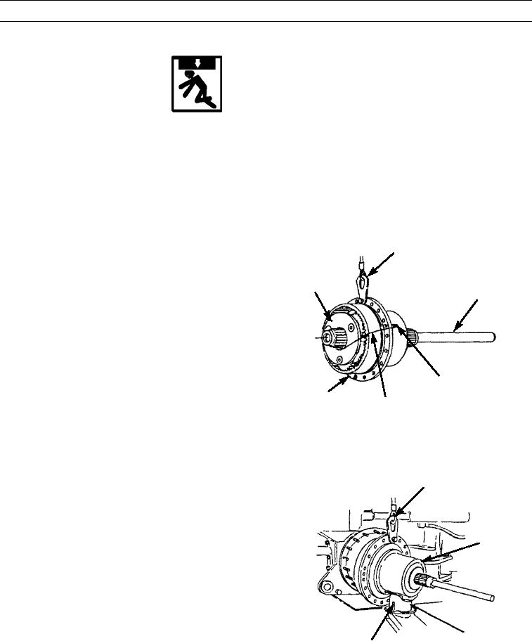
Attach link bracket and sling to planet carrier assem-
LINK BRACKET
bly (17) and position on saddle and floor jack. Put
AND SLING
axleshaft (18) in position in housing (19) to keep
planet carrier assembly in balance.
16.
Move planet carrier assembly (17) to bottom-rear-left
17
18
of machine.
17.
Remove wire and two 3/4-10NC forcing screws.
3/4-10 NC
19
FORCING SCREW
WIRE
397-4227
18.
Position planet carrier assembly (17) on studs of
LINK BRACKET
machine.
AND SLING
17
397-4226
SADDLE AND
FLOOR JACK
0309 00-12

