
TM 5-3805-261-23-2
LEANING WHEEL MECHANISM MAINTENANCE - CONTINUED
0303 00
ADJUSTMENT - CONTINUED
NOTE
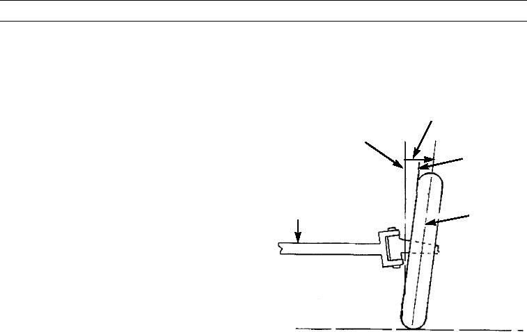
The camber angle and distance is shown on the inner side of the tire to better illustrate how the camber angle
is obtained.
3.
Measure distance from bottom of tire to plumb bob.
POSITIVE CAMBER
Distance should be 0.7 in. (18 mm) which indicates 2
VERTICAL LINE
degrees of positive camber.
CAMBER
4.
Check the other front tire using the same method. If
ANGLE
the camber is more or less than 2 degrees of positive
camber, lengthen or shorten lean bar so camber is cor-
rect on both wheels.
TIRE
AXLE
CENTERLINE
ROAD SURFACE
397-2238
END OF WORK PACKAGE
0303 00-10