
TM 5-3805-261-23-2
TRANSMISSION CONTROL RELIEF VALVE MAINTENANCE - CONTINUED
0296 00
TESTING - CONTINUED
1.
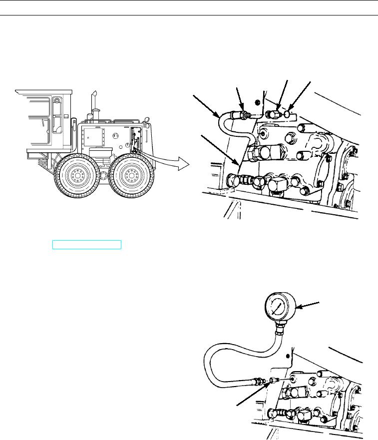
Disconnect hose assembly (1) from valve assembly (4).
2.
Remove elbow (2) and preformed packing (3). Discard preformed packing.
2
3
TO DIFFERENTIAL
1
LOCK VALVE
4
397-4133
3.
Use a 9/16-18 adapter to install 0 to 200 psi (0 to 1,379 kPa) pressure gauge.
4.
Start engine (TM 5-3805-261-10).
NOTE
Pressure gauge must read 75 psi (517 kPa). If not, replace control relief valve.
5.
Position transmission control lever in neutral. Read
0 TO 200 PSI
pressure gauge.
PRESSURE GAUGE
6.
Stop engine.
7.
Remove 0 to 200 psi (0 to 1,379 kPa) pressure gauge
and 9/16-18 adapter.
9/16 - 18
ADAPTER
397-4134
8.
Install new preformed packing (3) and elbow (2) on valve assembly (4).
9.
Connect hose assembly (1).
0296 00-2