TM 5-3805-261-23-1
HYDRAULIC CONTROL LEVERS REPLACEMENT - CONTINUED
0219 00
REMOVAL - CONTINUED
NOTE
13
12
14
11
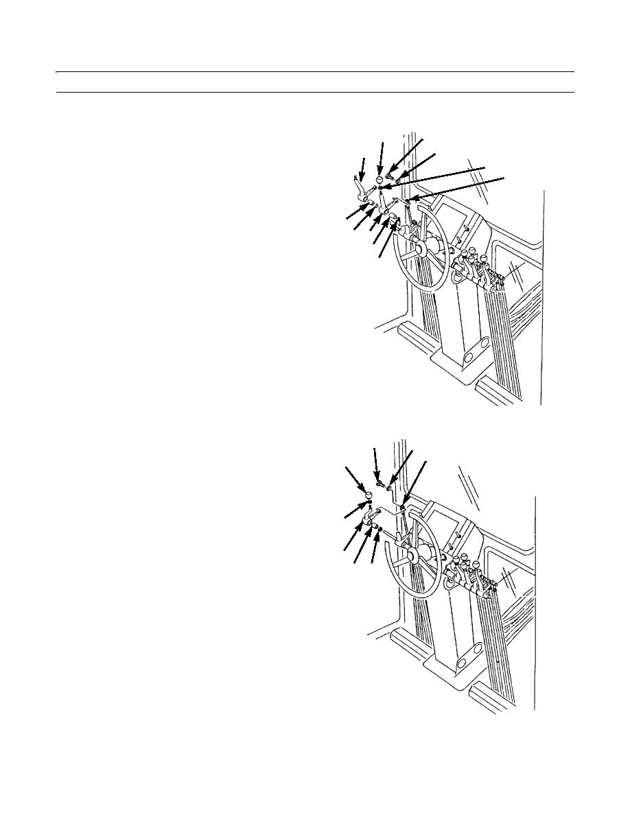
Tag levers before removing to aid in installation.
15
6.
Remove lever (11) and bearings (21 and 20).
16
7.
Remove bolt (13) and lockwasher (14). Discard lock-
washer.
8.
Disconnect linkage (16).
21
20 19
9.
Loosen nut (15).
18
10.
Remove sideshift knob (12) and nut (15).
17
11.
Remove lever (19) and bearings (18 and 17).
397-705
23
12.
Remove bolt (23) and lockwasher (24). Discard lock-
24
washer.
25
22
13.
Disconnect linkage (25).
14.
Loosen nut (29).
15.
Remove circle drive knob (22) and nut (29).
16.
Remove lever (28) and bearings (27 and 26).
29
28
26
27
397-706
0219 00-3


