TM 5-3805-261-23-1
STEERING CYLINDER REPLACEMENT - CONTINUED
0176 00
ADJUSTMENT
WARNING
Ensure the machine will not roll or shift. Secure with wood blocks. Failure to follow this warning may cause
injury or death to personnel.
1.
Install leaning wheel lock pin on front axle (TM 5-3805-261-10).
2.
Lift front of machine using hydraulic jack.
3.
Install jack stands at both ends of front axle.
4.
Turn front wheels in straight ahead position (TM 5-3805-261-10).
5.
Mark two front tires at center of tread while turning wheels.
6.
Measure distance of front axle between marks at forward point of tires.
7.
Measure distance of front axle at rear point of tires.
8.
Subtract the larger distance from the smaller distance to determine the amount of toe-in.
NOTE
The toe-in is correct if the front distance is 0.12 to 0.25 in. (3.0 to 6.4 mm) less than the rear distance.
29
9.
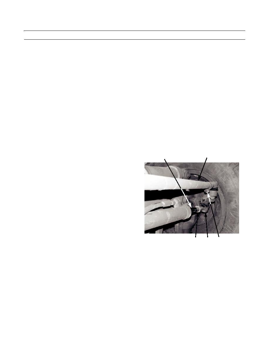
Loosen two nuts (30) on clamps at ends of tie-rod
28
(29).
10.
Turn rod until toe-in is 0.12 to 0.25 in. (3.0 to 6.4
mm). Tighten rod to 55 lb-ft (75 Nm).
11.
Loosen nut (24) and turn left cylinder shaft (28) all the
way on threaded rod of socket (27).
12.
Repeat step 11 for right steering cylinder.
13.
Turn cylinder shaft (28) until right spindle stop is 0.12
in. (3.0 mm) from right axle stop.
14.
Tighten nut (24) on cylinder shaft (28) to 250 lb-ft
(339 Nm).
397-2286
27
30
24
15.
Turn front wheels all the way to the right.
16.
Repeat step 15 so that right wheel spindle stop is 0.12 in. (3.0 mm) from left axle stop.
17.
Remove jack stands and hydraulic jack.
18.
Remove leaning wheel lock pin (TM 5-3805-261-10).
END OF WORK PACKAGE
0176 00-5


