TM 5-3805-261-23-1
RADIO INTERFERENCE SUPPRESSION REPLACEMENT
(MODELS 130G, 130GSCE, AND 130GNSCE) - CONTINUED
0146 00
REMOVAL
NOTE
To remove the horn radio interface suppression capacitor, perform steps 1 through 3. To remove the
alternator radio suppression capacitor, perform steps 4 through 7.
Tag all wire assemblies before disconnecting to aid in installation.
1.
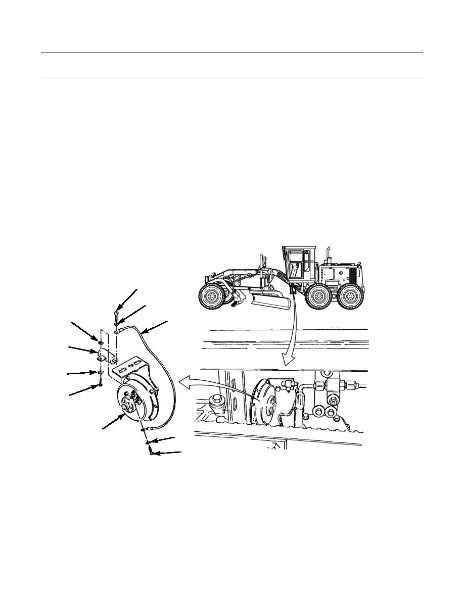
Remove screw (5) and lockwasher (4) and disconnect wire assembly (3) from horn (6) under front-left of cab. Discard
lockwasher.
2.
Remove screw (1), lockwasher (2), and wire assembly (3) from horn radio interface suppression capacitor (9). Discard
lockwasher.
3.
Remove bolt (7), lockwasher (8), horn radio interface suppression capacitor (9), and lockwasher (10). Discard lock-
washers.
1
2
10
3
9
8
7
6
4
5
397-431
4.
Disconnect wire assembly (19) from alternator (20).
5.
Remove screw (14) and lockwasher (15) and disconnect wire assemblies (13 and 16). Discard lockwasher.
6.
Remove screw (24), wire assembly (13), and lockwasher (23) from alternator radio suppression capacitor (22). Discard
lockwasher.
7.
Remove screw (11), lockwasher (12), disconnect wire assembly (17), remove lockwasher (18), alternator radio suppres-
sion capacitor (22), and lockwasher (21). Discard lockwashers.
0146 00-2


