TM 5-3805-261-20
HYDRAULIC SYSTEM MAINTENANCE. (cont)
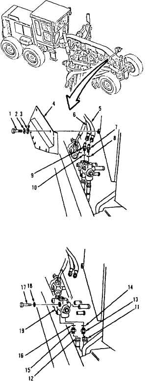
15-9.
Leaning Wheel Check Valve. (Sheet 2 of 4)
REMOVAL
1.
Remove nine bolts (1), washers (2 and 3)
and frame cover (4, Figure 15-10) in front,
right side of frame.
NOTE
All hose and tube assemblies must
be tagged before disconnecting to
aid in installation. Cap all hose and
tube ends to prevent contamination.
2.
Disconnect hose assemblies (5 and 6) from
top valve ports.
3.
Remove elbow (7) and preformed packing
(8). Discard preformed packing (8).
4.
Remove elbow (9) and preformed packing
(10). Discard preformed packing (10).
5.
Disconnect hose assemblies (11 and 12,
Figure 15-11) from bottom valve ports.
6.
Remove connector (13) and preformed
packing (14). Discard preformed packing
(14).
7.
Remove connector (15) and preformed
packing (16). Discard preformed packing
(16).
8.
Remove bolt (17), washer (18) and valve
assembly (19).
Figure 15-11.
Go to Sheet 3
Figure 15-10.
15-26