TM 5-3805-261-20
PRINCIPLES OF OPERATION.
1-24.
WHEELS AND TIRES. The six interchangeable rim and wheel assemblies are each mounted to the wheel spindle
flanges. Ten lug nuts are used to mount each wheel. Refer to paragraph 1-10 for location and paragraph 1-11 for tire
specifications.
1-25.
STEERING.
a.
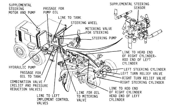
Steering (Figure 1-34). An engine driven, variable displacement pump mounted under the cab provides
hydraulic flow for the steering. Refer to paragraph 1-29. The steering wheel actuates a small hydraulic pump directing oil
to the two steering cylinders which steer the front wheels. An adjustable relief valve assembly is mounted at each side of
the chassis above the front axle. Refer to Appendix F for hydraulic system schematic. Also, refer to paragraph 1-21 for
location of hydraulic cylinders at front axle.
When the steering wheel is not being turned, the oil in lines and in cylinders, cannot move and the front wheels stay in
position. If the side of one of the front wheels hits a restriction (material that will not move), the positions of the front
wheels will move. The force on the side of the wheel causes an increase in the pressure of the oil in the cylinders and in
one of the lines to the cylinders. When the pressure of the oil in the line gets to 1700 psi, the relief valves opens. The high
pressure oil in the line goes through the open relief valve and into the other line to the cylinders. This lets the position of
the front wheels change.
Figure 1-34.
1-37


