TM 5-3805-261-20
PRINCIPLES OF OPERATION. (cont)
1-23.
AIR BRAKE SYSTEM.
a.
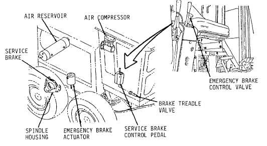
Air Compressor and Reservoir (Figure 1-33). A gear driven two cylinder air compressor mounted at the left
forward side of the engine provides air pressure for the service brakes. A dual section air reservoir is connected by air
lines and mounted under the rear of the vehicle. A governor controls the pressure.
Figure 1-33.
b.
Service Brakes. A foot pedal operated air valve in the cab directs air pressure through air lines for engaging
multiple oil disc brake assemblies for each wheel, within the tandem and spindle housings. Refer to Appendix F for air
system schematic.
c.
Parking/Emergency Brake. Multiple oil disc type located in the transmission case. Manually actuated by
forward movement of red lever on transmission control console. Lever engages parking brake and activates transmission
neutral lock to prevent machine movement. Brake is spring engaged and air disengaged. Can be used for emergency
stopping if air supply fails.
d.
Emergency Braking. Duel air system provides separate circuit at each tandem for safety. Malfunction of
one circuit leaves remaining circuit with at least half of original braking capacity. Refer to Appendix for air system
schematic.
e.
Blade Centershift Lock Pin. Though not part of the air brake system, the centershift lock pin is mentioned
here because it also is operated by the air supply from the air brake system. The centershift lock pin is part of the blade
system. Refer to paragraph 1-31 for location.
1-36