TM 5-3805-261-20
PRINCIPLES OF OPERATION.
1-26.
FRAME, TOWING ATTACHMENTS, DRAWBARS AND ARTICULATION SYSTEM.
c.
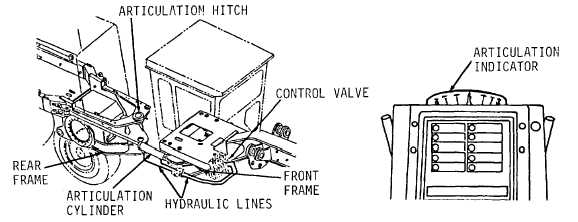
Articulation System (Figure 1-37). The front frame section and the frame and case (rear frame section) are
joined (hinged) at their hitch bushings. Two hydraulic cylinders and lines provide power for articulation. They are
controlled from the cab. One cylinder is mounted at each side of the front frame and extends to attach to the rear frame to
provide articulation control.
d.
Articulation Indicator (Figure 1-38). Mounted inside the cab at the top of the steering console. A small
housed cable mounted on the front frame attached to a lever fastened to the rear frame. When the frame is articulated the
cable moves the pointer on the indicator to show the amount of articulation. Refer to paragraph 1-31 for operation.
Figure 1-37
Figure 1-38
e.
Tow Pins and Brackets (Figure 1-39). There is one tow pin and bracket at the front of the 130G Grader and
one at the rear. The rear tow pin is held in its bracket by cross pin and cotter pin at the bottom of the tow pin. The front
tow pin is held in the bracket by a latch assembly at the top of the bracket. The front bracket is bolted to the frame. The
rear bracket is welded to the bumper assembly.
Figure 1-39.
1-39


