TM 5-3805-261-20
PRINCIPLES OF OPERATION. (cont)
1-18.
ELECTRICAL SYSTEM. (cont)
g.
Sending Units. (cont)
Name of Unit
Location
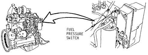
(11) Fuel pressure switch
Engine right front on secondary
for master fault light
fuel filter.
and alarm (Figure 1-25).
Figure 1-25.
h.
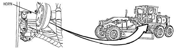
Horn and Horn Switch (Figure 1-26). 24 volt horn unit is located under the cab. Horn switch at center of
steering wheel applies voltage to horn when horn button is depressed. Light switch must be on to activate horn system.
Figure 1-26.
i.
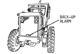
Back-up Alarm (Figure 1-27). Mounted on upper surface of rear bumper. Alarm is activated by a magnet
when transmission is placed in reverse. Loudness adjustment is mounted on the back of the alarm unit.
Figure 1-27.
1-32