TM 5-3805-261-20
PRINCIPLES OF OPERATION. (cont)
1-18.
ELECTRICAL SYSTEM. (cont)
g.
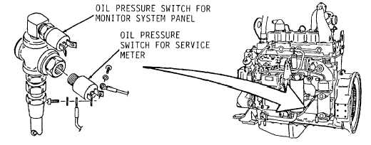
Sending Units.
Name of Unit
Location
(1)
Right side brake circuit
At brake pedal treadle valve.
air pressure for
Monitor System panel
(Figure 1-20)
(2)
Left side brake circuit
At brake pedal treadle valve.
air pressure for
Monitor System panel.
(3)
Stoplight switch.
At brake pedal treadle valve.
(4)
Blackout stoplight
At brake pedal treadle valve.
switch.
Figure 1-20.
(5)
Oil pressure switch for
Left side center of engine block.
servicemeter
(Figure 1-21).
(6)
Oil pressure switch for
Left side center of engine block.
Monitor System panel.
Figure 1-21.
1-30


