TM 5-3805-261-20
HYDRAULIC SYSTEM MAINTENANCE.
15-19.
Hydraulic Control Levers. (Sheet 3 of 11)
REMOVAL
6.
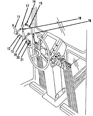
Remove lever (11) and bearings (12 and
13, Figure 15-38).
7.
Remove bolt (14) and lockwasher (15).
8.
Disconnect linkage (16).
9.
Loosen nut (18).
10.
Remove sideshift knob (17) and nut (18).
11.
Remove lever (19) and bearings (20 and
21).
12.
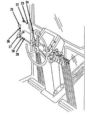
Remove bolt (22) and lockwasher (23,
Figure 15-39).
13.
Disconnect linkage (24).
14.
Loosen nut (26).
15.
Remove circle drive knob (25) and nut (26).
16.
Remove lever (27) and bearings (28 and
29).
Figure 15-38.
Figure 15-39.
Go to Sheet 4
15-75


