TM 5-3805-261-20
HYDRAULIC SYSTEM MAINTENANCE. (cont)
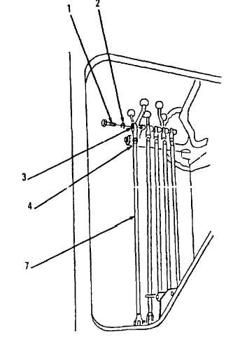
15-18.
Hydraulic Control Linkages. (Sheet 3 of 3)
INSTALLATION
1
Install rod (7), pin (6) and cotter pin (5,
Figure 15-36).
2.
Install nut (4) and rod end (3).
3.
Install lockwasher (2) and bolt (1).
ADJUSTMENT
NOTE
The
following
is
an
adjustment
procedure for the scarifier control
lever. The adjustment procedure for
the
remaining
control
levers
is
identical.
1.
Remove
bolt
(1,
Figure
15-36)
and
lockwasher (2) in steering console in cab.
2.
Loosen nut (4) on rod (7).
3.
Adjust rod end (3) on rod (7) so that bolt (1)
will slide through rod end (3) without putting
tension on bolt (1) when installed.
4.
Install lockwasher (2) and bolt (1).
5.
Tighten nut (4) on rod (7) against rod end
(3).
NOTE
Return
130G
Grader
to
original
equipment condition.
Figure 15-36.
End of Task
15-72