TM 5-3805-261-20
HYDRAULIC SYSTEM MAINTENANCE.
15-18.
Hydraulic Control Linkages. (Sheet 2 of 3)
REMOVAL
NOTE
The
following
is
a
maintenance
procedure for the scarifier control
lever. The maintenance procedure
for the remaining control levers is
identical.
1.
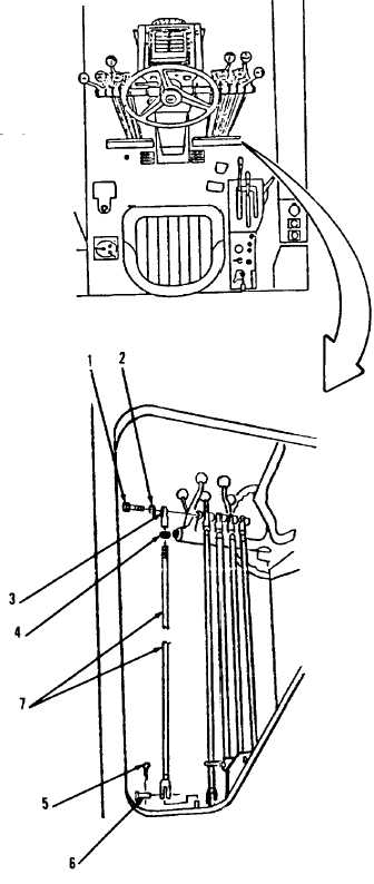
Remove bolt (1) and lockwasher (2, Figure
15-36) from steering console in cab.
2.
Remove rod end (3) and nut (4) from rod
(7).
NOTE
•
Control levers must be out of
alignment
to
provide
adequate
clearance for removal of pins and
bolts.
•
Tag both blade float control lever
pins to aid in installation.
3.
Remove cotter pin (5), pin (6) and rod (7).
Discard cotter pin (5).
CLEANING
Clean all parts. Refer to Chapter 2.
INSPECTION
Inspect all parts. Refer to Chapter 2.
Figure 15-36.
Go to Sheet 3
15-71

