TM 5-3805-261-20
HYDRAULIC SYSTEM MAINTENANCE. (cont.)
15-16.
Left Blade Lift Check and Relief Valve. (Sheet 3 of 4)
INSPECTION
Inspect all parts. Refer to Chapter 2.
INSTALLATION
1.
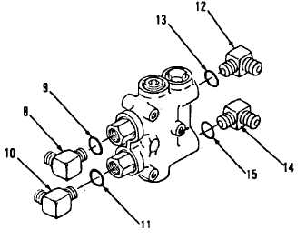
Install new preformed packing (15) and
elbow (14) to valve assembly (16, Figure
15-25).
2.
Install new preformed packing (13) and
elbow (12) to valve assembly (16).
3.
Install new preformed packing (11) and
elbow (10) to valve assembly (16).
4.
Install new preformed packing (9) and elbow
(8) to valve assembly (16).
5.
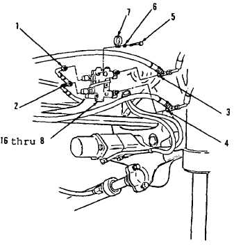
Position items 16 thru 8 as an assembly
(Figure 15-24) with two bolt holes facing
front of vehicle on left side of front frame.
6.
Install clamp (7), three washers (6) and
bolts (5).
7.
Connect tees (4 and 3).
8.
Connect hose assemblies (2 and 1).
Figure 15-25.
Figure 15-24.
Go to Sheet 4
15-56


