
2
TM 5-3805-293-23-5
FIELD MAINTENANCE
-
SCHEMATICS INTRODUCTION
0
350
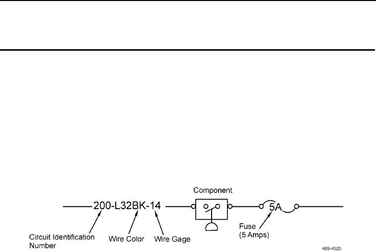
Each wire has a color and a number assigned to it (Figure 1). The following numbers identify wires generally as a
group.
1. 100 series wires are power circuits.
2. 200 series wires are ground circuits.
3. 300 series wires are machine basic circuits.
4. 400 series wires are monitoring circuits.
5. 500 series wires are accessory circuits.
6. 600 series wires are lighting circuits.
7. 700 to 999 series wires are control circuits.
Understanding the general usage of wires will aid in understanding the machine during troubleshooting.
Figure 1. Wire Identification.
0350
END OF TASK
END OF WORK PACKAGE