
TM 5-3805-293-23-5
0332
INSTALLATION CONTINUED
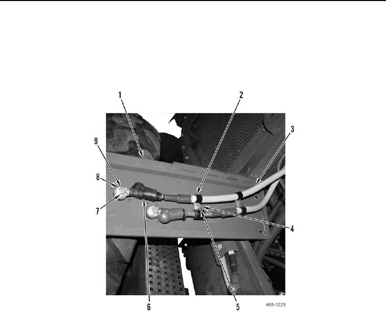
2. Install battery cables (Figure 6, Item 3), four clips (Figure 6, Item 2), two washers (Figure 6, Item 5) and bolts
(Figure 6, Item 4) on engine enclosure panel (Figure 6, Item 1).
3. Install two battery cables (Figure 6, Item 3), washers (Figure 6, Item 8), and bolts (Figure 6, Item 7) on junction
blocks (Figure 6, Item 9).
4. Position two boots (Figure 6, Item 6) over bolts (Figure 6, Item 7).
Figure 6. Interior Battery Cables.
0332