
TM 5-3805-293-23-5
0320
INSTALLATION CONTINUED
000320
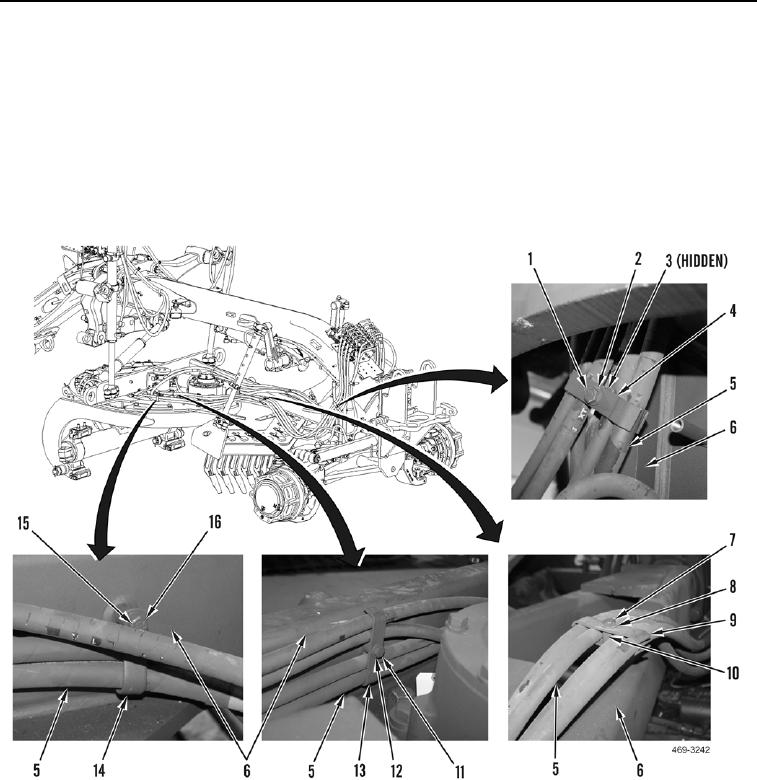
5. Install clamp (Figure 6, Item 14), washer (Figure 6, Item 16), and bolt (Figure 6, Item 15) on hose (Figure 6,
Item 5) and right side of machine (Figure 6, Item 6).
6. Install clamp (Figure 6, Item 13), washer (Figure 6, Item 12), and bolt (Figure 6, Item 11) on hose (Figure 6,
Item 4) and right side of machine (Figure 6, Item 6).
7. Install clamp (Figure 6, Item 9), spacer (Figure 6, Item 10), washer (Figure 6, Item 8), and bolt (Figure 6,
Item 7) on hose (Figure 6, Item 5) and right side of machine (Figure 6, Item 6).
8. Install clamp (Figure 6, Item 4), spacer (Figure 6, Item 3), washer (Figure 6, Item 2), and bolt (Figure 6, Item 1)
on hose (Figure 6, Item 5) and right side of machine (Figure 6, Item 6).
Figure 6. Right-Side Hose Clamps.
0320