
TM 5-3805-293-23-5
0316
INSTALLATION
000316
N OT E
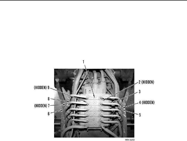
Install all lines as marked and tagged during removal.
1. Install new O-ring (Figure 7, Item 9) and connect tube (Figure 7, Item 8) to front valve (Figure 7, Item 1).
2. Install new O-ring (Figure 7, Item 7) and connect hose (Figure 7, Item 6) to tube (Figure 7, Item 8).
3. Install new O-ring (Figure 7, Item 2) and connect tube (Figure 7, Item 3) to front valve (Figure 7, Item 1).
4. Install new O-ring (Figure 7, Item 4) and connect hose (Figure 7, Item 5) to tube (Figure 7, Item 3).
Figure 7. Front Valve.
0316