
TM 5-3805-293-23-5
0306
INSTALLATION CONTINUED
000306
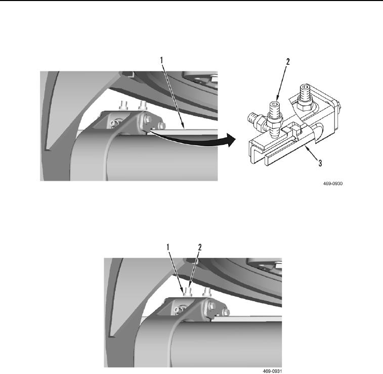
6. Adjust setscrews (Figure 10, Item 2) to obtain clearance of 0.005 to 0.035 in. (0.13 to 0.89 mm) between blade
rail (Figure 10, Item 1) and wearstrips (Figure 10, Item 3).
Figure 10. Upper Wearstrip Plate Adjustment.
0306
7. Install six new locknuts (Figure 11, Item 1) on setscrews (Figure 11, Item 2). Tighten locknuts to 184 lb-ft
(250 Nm).
Figure 11. Locknuts.
0306
END OF TASK
FOLLOW-ON TASKS
000306
1. Remove articulation lock pin (TM 5-3805-293-10).
2. Lower blade/moldboard to ground (TM 5-3805-293-10).
END OF TASK
END OF WORK PACKAGE