
TM 5-3805-293-23-5
0300
ASSEMBLY CONTINUED
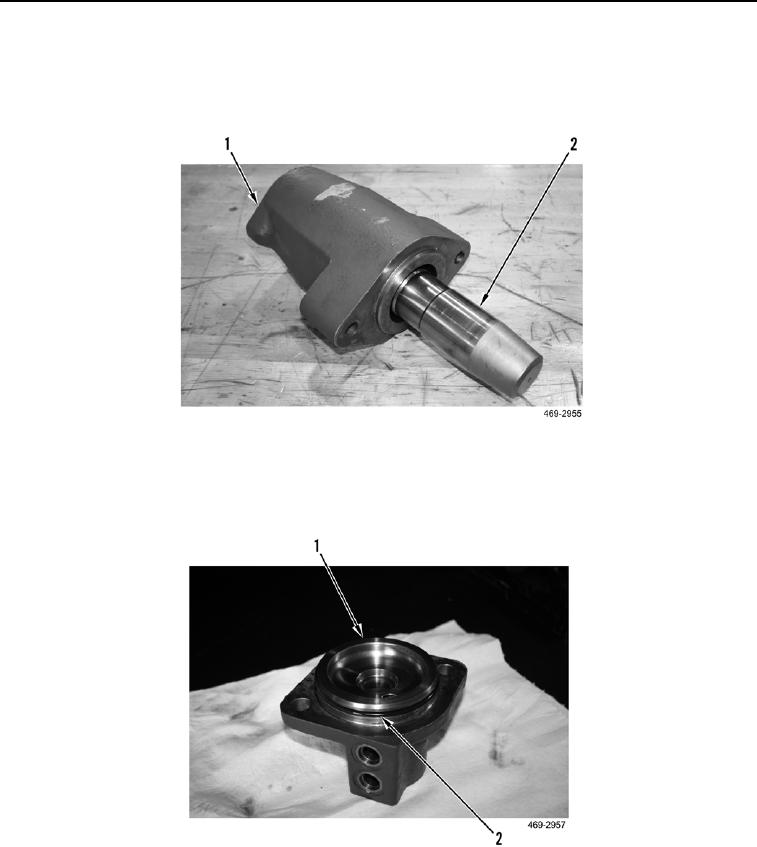
5. Apply a light coating of hydraulic fluid on centershift lock cylinder housing (Figure 9, Item 1).
6. Using a plastic hammer or mallet, install centershift lock piston (Figure 9, Item 2) in centershift lock cylinder
housing (Figure 9, Item 1).
Figure 9. Centershift Lock Cylinder Piston.
0300
7. Apply a light coating of hydraulic fluid on O-ring (Figure 10, Item 2).
8. Install new O-ring (Figure 10, Item 2) on centershift lock cylinder cap (Figure 10, Item 1).
Figure 10. Centershift Lock Cap and O-ring.
0300