
TM 5-3805-293-23-5
0291
INSTALLATION
000291
N OT E
Install wires as noted during removal.
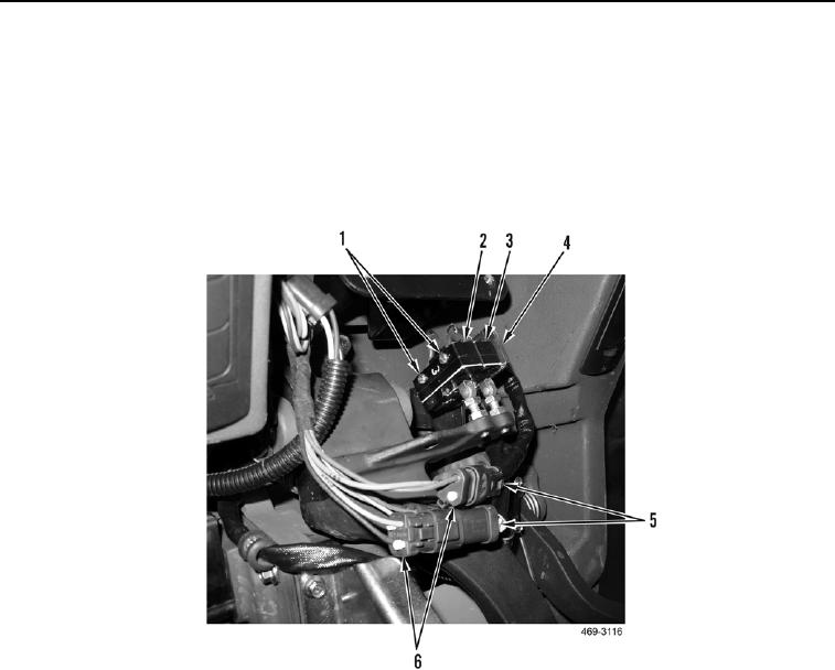
1. Install brake light limit switch (Figure 4, Item 3), brake pedal limit switch (Figure 4, Item 2), and two screws
(Figure 4, Item 1) on bracket (Figure 4, Item 4).
2. Connect two electrical connectors (Figure 4, Item 5) to lower cab harness (Figure 4, Item 6).
Figure 4. Brake Pedal Switches.
0291