
TM 5-3805-293-23-5
0290
INSPECTION
000290
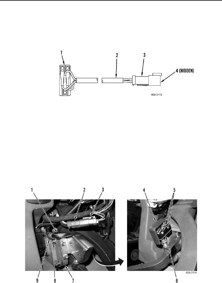
1. Inspect connector pins (Figure 3, Item 4) for damage.
2. Inspect switch electrical connector (Figure 3, Item 3) for damage.
3. Inspect switch insulation and wires (Figure 3, Item 2) for damage.
4. Inspect switch housing (Figure 3, Item 1) for damage.
Figure 3. Switch Inspection.
0290
END OF TASK
INSTALLATION
000290
N OT E
Install wires as noted during removal.
1. Install inching pedal switch (Figure 4, Item 6) and two screws (Figure 4, Item 5) on bracket (Figure 4, Item 4).
2. Install clamp (Figure 4, Item 9) and bolt (Figure 4, Item 8) on harness (Figure 4, Item 1) and pedal assembly
(Figure 4, Item 7).
3. Connect electrical connector (Figure 4, Item 2) to lower cab harness (Figure 4, Item 3).
Figure 4. Inching Pedal Switch.
0290