
TM 5-3805-293-23-5
0290
REMOVAL CONTINUED
000290
N OT E
Tag and mark wires to aid in installation.
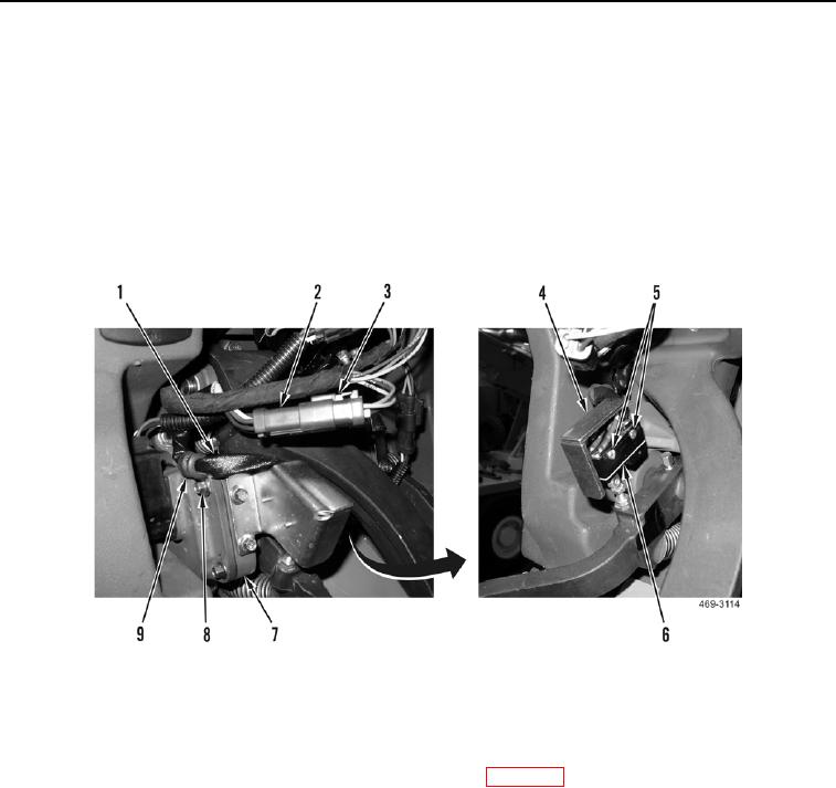
2. Disconnect electrical connector (Figure 2, Item 2) from lower cab harness (Figure 2, Item 3).
3. Remove bolt (Figure 2, Item 8) and clamp (Figure 2, Item 9) from harness (Figure 2, Item 1) and pedal
assembly (Figure 2, Item 7).
4. Remove two screws (Figure 2, Item 5) and inching pedal switch (Figure 2, Item 6) from bracket (Figure 2,
Item 4).
Figure 2. Inching Pedal Switch.
0290
END OF TASK
CLEANING
000290
Clean all parts IAW Mechanical General Maintenance Instructions (WP 0346).
END OF TASK