
TM 5-3805-293-23-5
0284
ASSEMBLY CONTINUED
N OT E
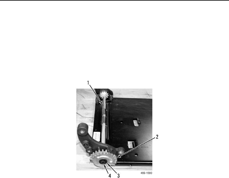
Position the recliner shaft so that the roll pins are on top of the spring when viewed from
the top. The recliner shaft may need to be rotated slightly in order for the recliner latch
gear to engage the shaft and the limit tab on the recliner bracket. The gear teeth of the
recliner gear should face upward, and spring tension should be felt when rotating the
recliner gear clockwise (right).
7. Install recliner latch gear (Figure 24, Item 2) on recliner shaft (Figure 24, Item 1).
8. Install washer (Figure 24, Item 3) and bolt (Figure 24, Item 4) on recliner latch gear (Figure 24, Item 2).
Figure 24. Recliner Latch Gear.
0284