
28
TM 5-3805-293-23-5
FIELD MAINTENANCE
-
SEAT ASSEMBLY REPAIR
0
284
Removal, Disassembly, Cleaning and Inspection, Assembly, Installation
INITIAL SETUP
References
Tools and Special Tools
0
0
Tool Kit, General Mechanic's
0
(WP 0354, Item 83)
0
Equipment Condition
0
Screwdriver Attachment, Torx Bit, 3/8" Dr,
Machine parked (TM 5-3805-293-10)
T-30 (S0388) (WP 0354, Item 85)
0
0
Drawings Required
Materials/Parts
0
0
TM 5-3805-293-24P, Figure 141
Sealing Compound (WP 0355, Item 28)
0
0
Strap, Tiedown, Electrical Component
Estimated Time to Complete
0
(WP 0355, Item 33)
0
4.0 Hr
0
Push Washer (2)
0
Personnel Required
0
Two
0
REMOVAL
000284
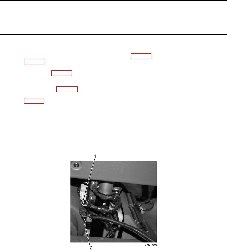
1. Disconnect operator in-seat switch harness connector (Figure 1, Item 2) from harness (Figure 1, Item 1).
Figure 1. Operator In-Seat Switch Connector.
0284