
TM 5-3805-293-23-5
0283
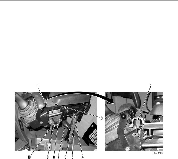
INSTALLATION CONTINUED
C AU T I O N
The joystick support mount is spring-loaded. Maintain slight downward pressure on the
joystick support device until the locking device has engaged the joystick support tube.
5. Install joystick support (Figure 41, Item 4) on mount (Figure 41, Item 5).
6. Tighten joystick support height adjustment locking knob (Figure 41, Item 6).
7. Position wiring harness (Figure 41, Item 9) on joystick support (Figure 41, Item 4).
8. Connect connector (Figure 41, Item 2) to turn signal switch (Figure 41, Item 1).
9. Install turn signal switch (Figure 41, Item 1) on outer panel cover (Figure 41, Item 3).
10. Connect horn switch connector (Figure 41, Item 10) to harness (Figure 41, Item 9).
11. Connect two joystick control harness connectors (Figure 41, Item 7) to harness (Figure 41, Item 9).
12. Install tiedown straps (Figure 41, Item 8) on harness (Figure 41, Item 9).
Figure 41. Joystick Control Harness Connectors.
0283