
TM 5-3805-293-23-5
0283
ASSEMBLY CONTINUED
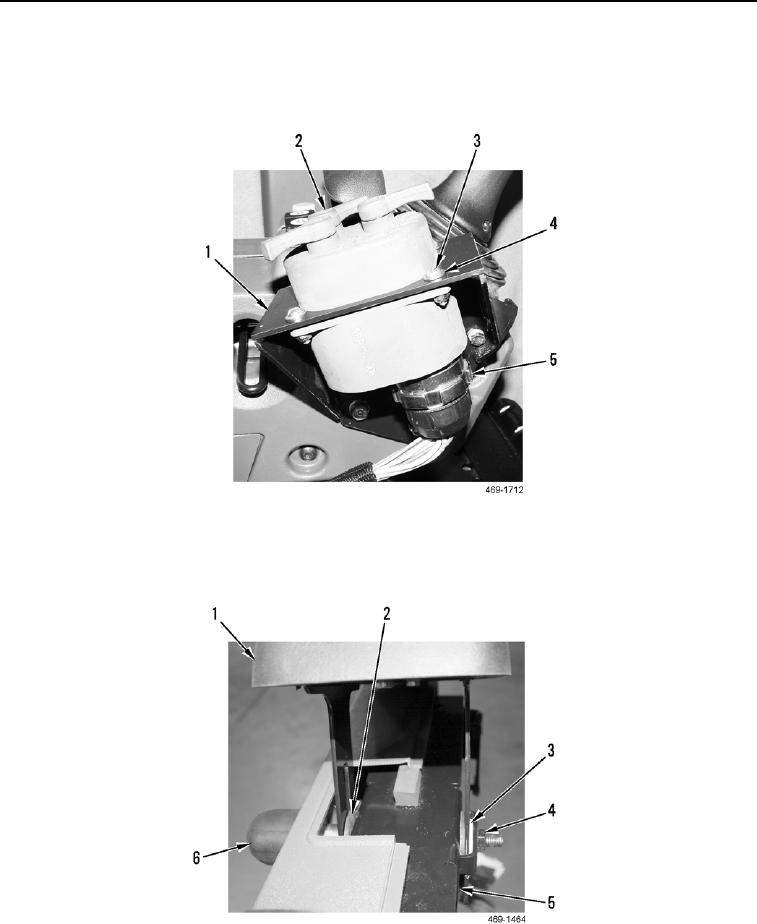
20. Install control indicator (Figure 36, Item 2), four washers (Figure 36, Item 4), and screws (Figure 36,
Item 3) on control indicator bracket (Figure 36, Item 1).
21. Connect control indicator harness connector (Figure 36, Item 5) to control indicator (Figure 36, Item 2).
Figure 36. Control Indicator.
0283
22. Install armrest (Figure 37, Item 1), two washers (Figure 37, Item 3), two rubber washers (Figure 37, Item 2),
lock bolt (Figure 37, Item 6), and nut plate (Figure 37, Item 4) on joystick support (Figure 37, Item 5).
Figure 37. Armrest.
0283