
TM 5-3805-293-23-5
0283
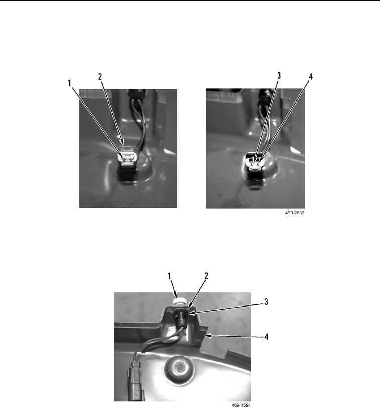
ASSEMBLY CONTINUED
16. Install two horn switch wires (Figure 33, Item 4) in harness connector (Figure 33, Item 2), and use removal tool
to press two horn switch wires to engage two tabs (Figure 33, Item 3).
17. Install wedge (Figure 33, Item 1) in harness connector (Figure 33, Item 2) using removal tool.
Figure 33. Horn Switch Harness Connector.
0283
18. Install horn switch (Figure 34, Item 1), new lockwasher (Figure 34, Item 2), and nut (Figure 34, Item 3) on
joystick support cover (Figure 34, Item 4).
Figure 34. Horn Switch.
0283