
TM 5-3805-293-23-5
0277
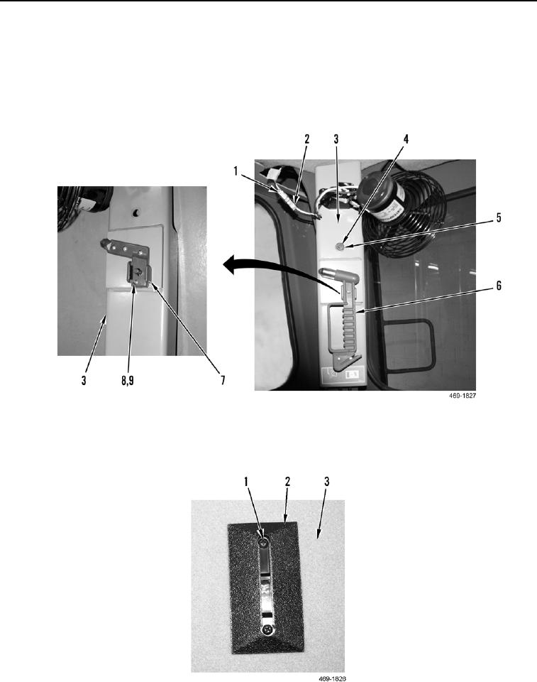
INSTALLATION CONTINUED
15. Install mount (Figure 25, Item 7), four washers (Figure 25, Item 9), and screws (Figure 25, Item 8) on trim plate
(Figure 25, Item 3).
16. Install trim plate (Figure 25, Item 3), two washers (Figure 25, Item 5), and bolts (Figure 25, Item 4) on cab.
17. Install glass breakage escape tool (Figure 25, Item 6) on trim plate (Figure 25, Item 3).
18. Connect fan connector (Figure 25, Item 2) to harness (Figure 25, Item 1).
Figure 25. Trim Plate.
0277
19. Install two joystick illumination lights (Figure 26, Item 2) and four screws (Figure 26, Item 1) on center
headliner access panel (Figure 26, Item 3).
Figure 26. Joystick Illumination Lights.
0277