
TM 5-3805-293-23-4
0275
INSTALLATION CONTINUED
000275
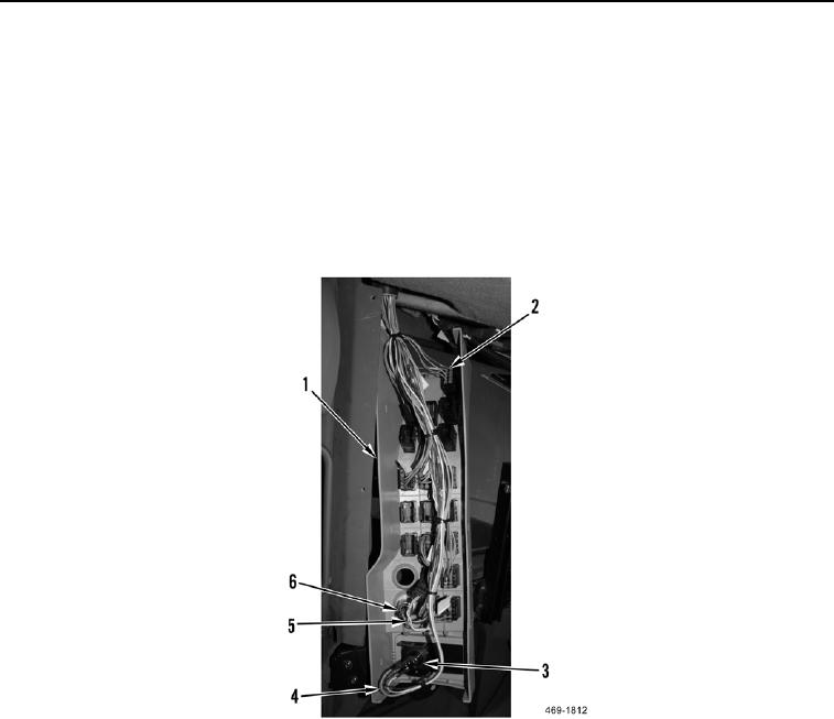
12. Install control switch panel (Figure 19, Item 1) on machine.
N OT E
Install terminal and connectors as tagged during removal.
13. Connect eight harness connectors (Figure 19, Item 2) to control switch panel (Figure 19, Item 1).
14. Connect three spade terminals (Figure 19, Item 4) to coolant heater switch (Figure 19, Item 3).
15. Connect upper cab harness connector (Figure 19, Item 5) to 12 volt power outlet (Figure 19, Item 6).
Figure 19. Control Switch Panel Electrical Connections.
0275

