
TM 5-3805-293-23-4
0275
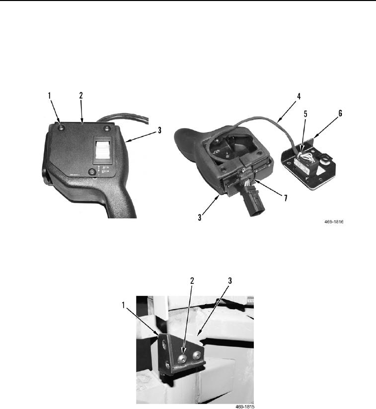
INSTALLATION CONTINUED
000275
3. Install scarifier control switch (Figure 15, Item 5) on scarifer control switch panel (Figure 15, Item 6).
4. Install wiring harness (Figure 15, Item 4) and grommet (Figure 15, Item 7) on scarifier control switch panel
housing (Figure 15, Item 3).
5. Install switch panel (Figure 15, Item 2) and three screws (Figure 15, Item 1) on scarifier control switch panel
housing (Figure 15, Item 3).
Figure 15. Scarifier Control Switch Panel Housing.
0275
6. Install bracket (Figure 16, Item 1) and two screws (Figure 16, Item 2) on cab (Figure 16, Item 3).
Figure 16. Scarifier Control Switch Panel Bracket.
0275

