
TM 5-3805-293-23-4
0275
INSTALLATION CONTINUED
000275
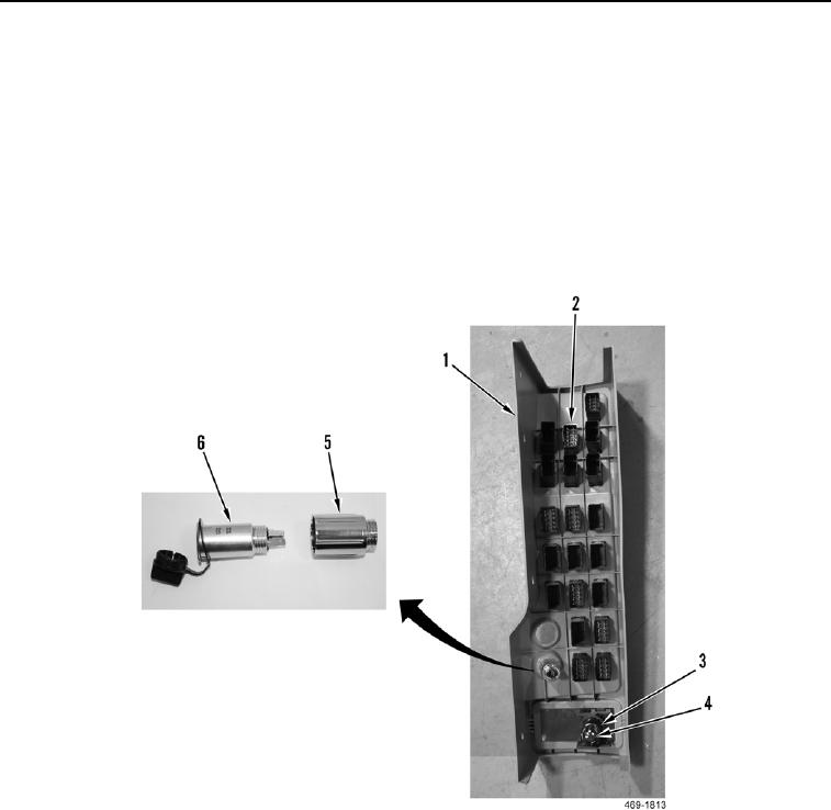
9. Install 12 volt power supply socket (Figure 18, Item 3) and sleeve (Figure 18, Item 4) on control switch panel
(Figure 18, Item 1).
10. Install coolant heater switch (Figure 18, Item 5) and nut (Figure 18, Item 6) on control switch panel (Figure 18,
Item 1).
N OT E
Install switches as tagged during removal.
Install blank covers on panel if removed.
11. Install eight control rocker switches (Figure 18, Item 2) on control switch panel (Figure 18, Item 1).
Figure 18. Control Switch.
0275

