
TM 5-3805-293-23-4
0266
INSTALLATION CONTINUED
000266
N OT E
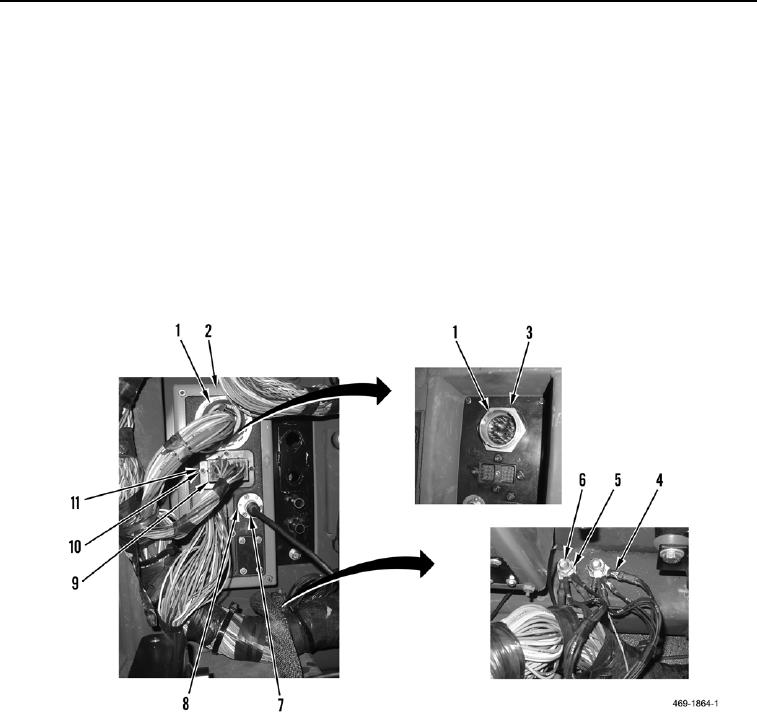
Route harness on machine as noted during removal.
4. Position harness in machine.
5. Connect camera cable (Figure 14, Item 7) to bulkhead connector (Figure 14, Item 8).
6. Remove two nuts (Figure 14, Item 6), washers (Figure 14, Item 5), and nine ground eyelets (Figure 14, Item 4)
from rear bulkhead (Figure 14, Item 2).
7. Install two cab lower wiring harness connectors (Figure 14, Item 9), eight washers (Figure 14, Item 10), and
screws (Figure 14, Item 11) on rear bulkhead (Figure 14, Item 2).
8. Install cab lower wiring harness connector (Figure 14, Item 1) and nut (Figure 14, Item 3) on rear bulkhead
(Figure 14, Item 2).
Figure 14. Rear Bulkhead Internal Connections.
0266

