
TM 5-3805-293-23-4
0266
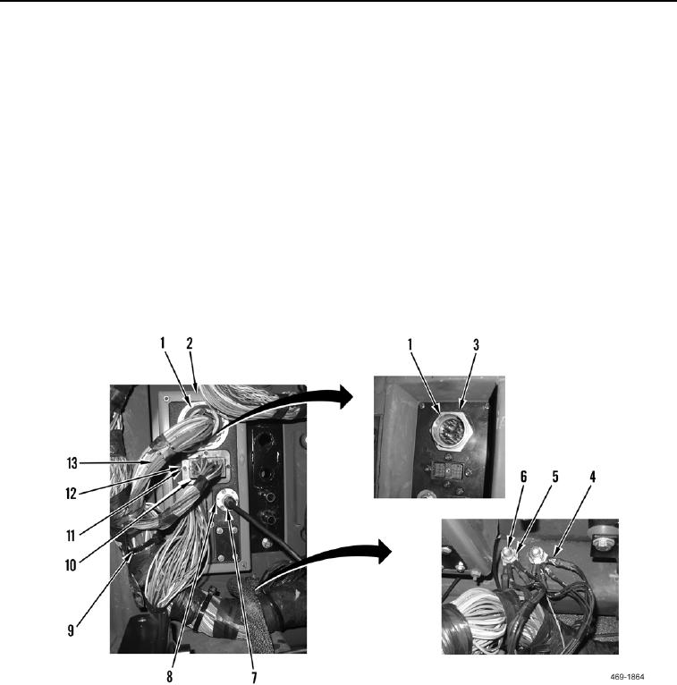
REMOVAL CONTINUED
20. Remove nut (Figure 10, Item 3) and cab lower wiring harness connector (Figure 10, Item 1) from rear bulkhead
(Figure 10, Item 2).
21. Remove eight screws (Figure 10, Item 11), washers (Figure 10, Item 12), and two cab lower wiring harness
connectors (Figure 10, Item 10) from rear bulkhead (Figure 10, Item 2).
22. Disconnect camera cable (Figure 10, Item 7) from bulkhead connector (Figure 10, Item 8).
23. Remove two nuts (Figure 10, Item 6), washers (Figure 10, Item 5), and nine ground eyelets (Figure 10, Item 4)
from rear bulkhead (Figure 10, Item 2).
N OT E
Note routing of harness prior to removal to aid in installation.
Note location of tiedown straps prior to removal to aid in installation.
24. Remove tiedown straps (Figure 10, Item 9) securing cab lower harness (Figure 10, Item 13) in cab. Discard
tiedown straps.
25. Remove cab lower harness (Figure 10, Item 13) from machine.
Figure 10. Rear Bulkhead Internal Connections.
0266

