
TM 5-3805-293-23-4
0256
INSTALLATION
000256
N OT E
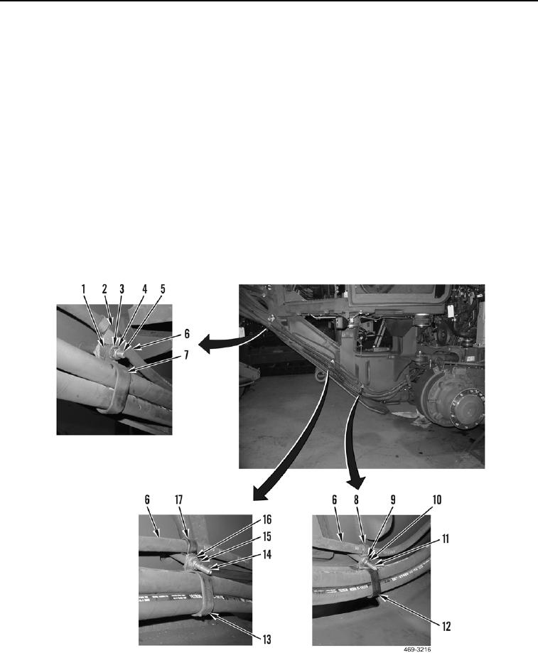
Install all lines as tagged during removal.
1. Position tube (Figure 6, Item 1) on machine. Install new O-ring (Figure 6, Item 2) and connect tube to rear
valve (Figure 6, Item 3).
2. Install two clamps (Figure 6, Item 6), spacer (Figure 6, Item 5), clamp (Figure 6, Item 9), washer (Figure 6,
Item 10), and nut (Figure 6, Item 4) on tube (Figure 6, Item 1) and stud (Figure 6, Item 11).
3. Route hose (Figure 6, Item 8) on machine. Install new O-ring (Figure 6, Item 7), and connect hose to tube
(Figure 6, Item 1).
4. Install two clamps (Figure 7, Item 7), spacer (Figure 7, Item 1), clamp (Figure 7, Item 2), washer (Figure 7,
Item 3), and new locknut (Figure 7, Item 4) on hose (Figure 7, Item 6) and stud (Figure 7, Item 5).
5. Install two clamps (Figure 7, Item 17), clamp (Figure 7, Item 13), washer (Figure 7, Item 16), and new locknut
(Figure 7, Item 15) on hose (Figure 7, Item 6) and stud (Figure 7, Item 14).
6. Install two clamps (Figure 7, Item 8), clamp (Figure 7, Item 12), washer (Figure 7, Item 9), and new locknut
(Figure 7, Item 10) on hose (Figure 7, Item 6) and studs (Figure 7, Item 11).
Figure 7. Left-Side Hose Clamps.
0256

