
TM 5-3805-293-23-4
0254
INSTALLATION CONTINUED
000254
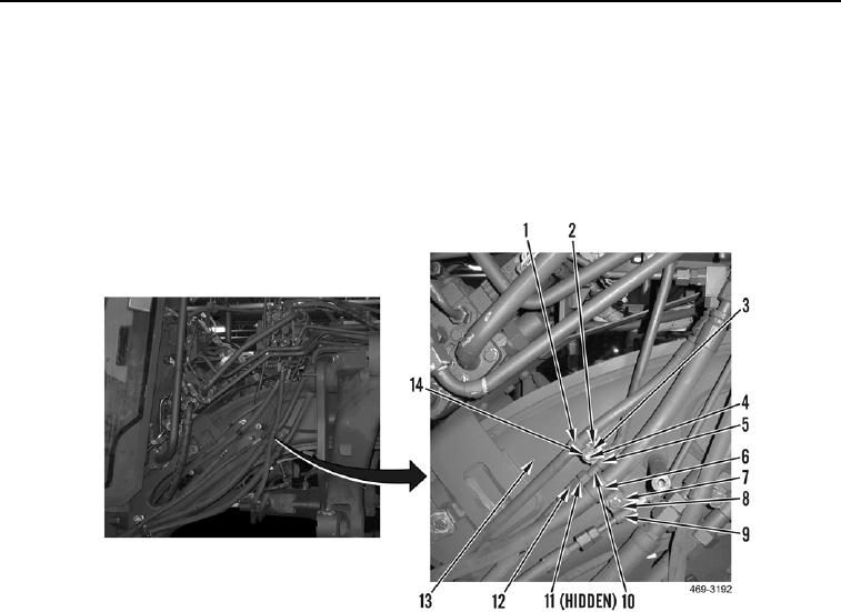
2. Install clamp (Figure 8, Item 5), spacer (Figure 8, Item 2), clamp (Figure 8, Item 1), washer (Figure 8, Item 14),
and nut (Figure 8, Item 3) on tube (Figure 8, Item 10) and stud (Figure 8, Item 4).
3. Route hose (Figure 8, Item 12) on machine. Install new O-ring (Figure 8, Item 11) and connect hose to tube
(Figure 8, Item 10).
4. Install clamp (Figure 8, Item 9), clamp (Figure 8, Item 6), washer (Figure 8, Item 7), and bolt (Figure 8, Item 8)
on frame (Figure 8, Item 13).
Figure 8. Right-Side Rear Valve.
0254

