
TM 5-3805-293-23-4
0243
INSTALLATION CONTINUED
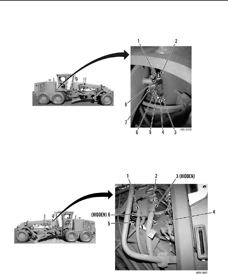
27. Install three blocks (Figure 24, Item 6), two washers (Figure 24, Item 3), bolts (Figure 24, Item 4), plate
(Figure 24, Item 8), two washers (Figure 24, Item 1), and new locknuts (Figure 24, Item 2) on five hoses
(Figure 24, Item 7) and plate (Figure 24, Item 5).
Figure 24. Flex Joint Blocks.
0243
28. Install new O-ring (Figure 25, Item 6) and connect hose (Figure 25, Item 5) to elbow (Figure 25, Item 1).
29. Install new O-ring (Figure 25, Item 3) and connect hose (Figure 25, Item 4) to elbow (Figure 25, Item 2).
Figure 25. Left-Side Steering Control Valve.
0243

