
TM 5-3805-293-23-4
0232
INSTALLATION CONTINUED
N OT E
Install all hoses as tagged during removal.
Route hoses on machine as noted during removal.
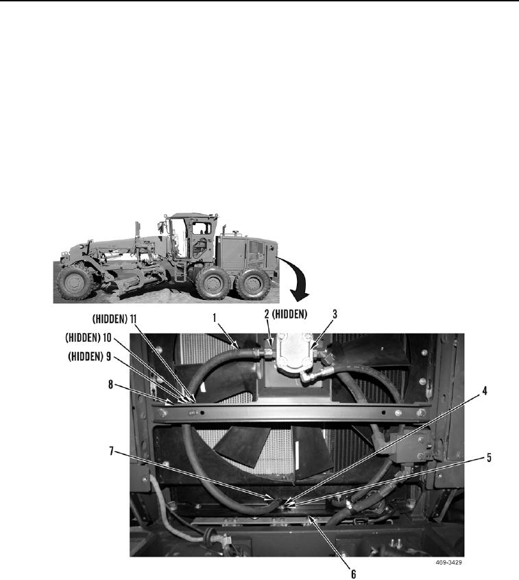
2. Install hose (Figure 14, Item 1) on machine.
3. Install new O-ring (Figure 14, Item 2) and connect hose (Figure 14, Item 1) to cooling fan gear motor
(Figure 14, Item 3).
4. Install clamp (Figure 14, Item 7), washer (Figure 14, Item 5), and bolt (Figure 14, Item 4) on hose (Figure 14,
Item 1) and fan frame (Figure 14, Item 6).
5. Install clamp (Figure 14, Item 11), washer (Figure 14, Item 10), and bolt (Figure 14, Item 9) on hose (Figure 14,
Item 1) and crossbeam (Figure 14, Item 8).
Figure 14. Fan.
0232

