
TM 5-3805-293-23-4
0231
INSTALLATION CONTINUED
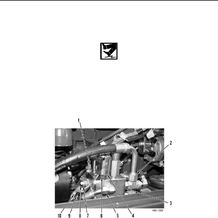
10. Install retainer (Figure 12, Item 9), washer (Figure 12, Item 7), nut (Figure 12, Item 8), and new tiedown strap
(Figure 12, Item 10) on hydraulic fan and brake control manifold (Figure 12, Item 3).
11. Connect hydraulic fan solenoid connector (Figure 12, Item 6) to hydraulic fan solenoid (Figure 12, Item 4).
WARN I N G
Hydraulic oil is very slippery. Immediately wipe up any spills. Failure to follow this warning
may result in injury to personnel.
12. Connect cooling fan hydraulic oil line (Figure 12, Item 2) to hydraulic fan and brake control manifold (Figure 12,
Item 3).
13. Connect hydraulic load sense line (Figure 12, Item 5) to hydraulic fan and brake control manifold (Figure 12,
Item 3).
14. Connect hydraulic oil return line (Figure 12, Item 1) to hydraulic fan and brake control manifold (Figure 12,
Item 3).
Figure 12. Hydraulic Fan and Brake Control Manifold Line.
0231

