
TM 5-3805-293-23-4
0228
INSTALLATION
000228
N OT E
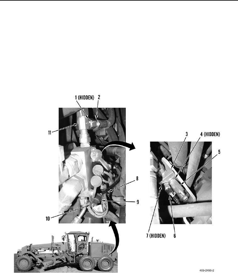
Install wires as noted during removal.
1. Install new O-ring (Figure 5, Item 7) and main hydraulic pump discharge pressure sensor (Figure 5, Item 6) on
implement steering control manifold (Figure 5, Item 3).
2. Connect electrical connector (Figure 5, Item 9) to rear chassis wiring harness (Figure 5, Item 10).
3. Install new tiedown strap (Figure 5, Item 8) on rear chassis wiring harness (Figure 5, Item 10).
4. Install new O-ring (Figure 5, Item 4) and pressure relief valve (Figure 5, Item 5) on implement steering control
manifold (Figure 5, Item 3).
5. Install new O-ring (Figure 5, Item 1) and hose (Figure 5, Item 2) on tee fitting (Figure 5, Item 11).
Figure 5. Pressure Sensor.
00228

