
TM 5-3805-293-23-4
0226
REMOVAL CONTINUED
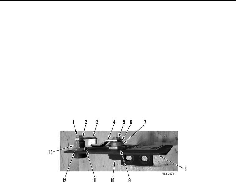
2. Remove screw (Figure 10, Item 1), lockwasher (Figure 10, Item 2), and locking latch (Figure 10, Item 3) from
locking latch cylinder (Figure 10, Item 13). Discard lockwasher.
3. Unlock locking tab washer (Figure 10, Item 11) from nut (Figure 10, Item 12).
4. Remove nut (Figure 10, Item 12), locking tab washer (Figure 10, Item 11), and locking latch cylinder (Figure
10, Item 13) from access door (Figure 10, Item 8).
N OT E
Note the direction of coolant tank access door handle and latch to aid in installation.
5. Remove bolt (Figure 10, Item 5), latch (Figure 10, Item 4), detent washer (Figure 10, Item 6) and handle
(Figure 10, Item 10) from handle latch cylinder (Figure 10, Item 7).
6. Remove nut (Figure 10, Item 9) and handle latch cylinder (Figure 10, Item 7) from access door (Figure 10,
Item 8).
7. Clean and inspect coolant tank access door and hardware (refer to Cleaning and Inspection in this work
package).
Figure 10. Coolant Tank Access Door Hardware.
0226
END OF TASK

