
TM 5-3805-293-23-4
0222
ASSEMBLY CONTINUED
000222
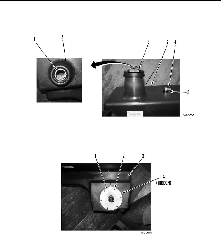
5. Install strainer (Figure 13, Item 1) and filler cap (Figure 13, Item 3) on hydraulic tank (Figure 13, Item 2).
6. Install new grommet (Figure 13, Item 5) and fitting (Figure 13, Item 4) on hydraulic tank (Figure 13, Item 2).
Figure 13. Filler Cap.
0222
7. Install new O-ring (Figure 14, Item 4), tube assembly (Figure 14, Item 1), and six bolts (Figure 14, Item 2) on
hydraulic tank (Figure 14, Item 3).
Figure 14. Tube Assembly.
0222

