
TM 5-3805-293-23-4
0212
INSTALLATION CONTINUED
N OT E
Install all lines as marked and tagged during removal.
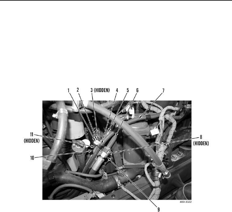
10. Route hose (Figure 21, Item 10) on machine.
11. Install new O-ring (Figure 21, Item 11) and connect hose (Figure 21, Item 10) to tube (Figure 21, Item 5).
12. Route hose (Figure 21, Item 9) on machine.
13. Install new O-ring (Figure 21, Item 8) and connect hose (Figure 21, Item 9) to tube (Figure 21, Item 6).
14. Install two clamps (Figure 21, Item 4), washer (Figure 21, Item 2), bolt (Figure 21, Item 1), washer (Figure 21,
Item 2), and nut (Figure 21, Item 3) on hose (Figure 21, Item 7) and tube (Figure 21, Item 5).
Figure 21. AWD Pump Left-Side Hose Connections.
0212

