
TM 5-3805-293-23-4
0180
REMOVAL CONTINUED
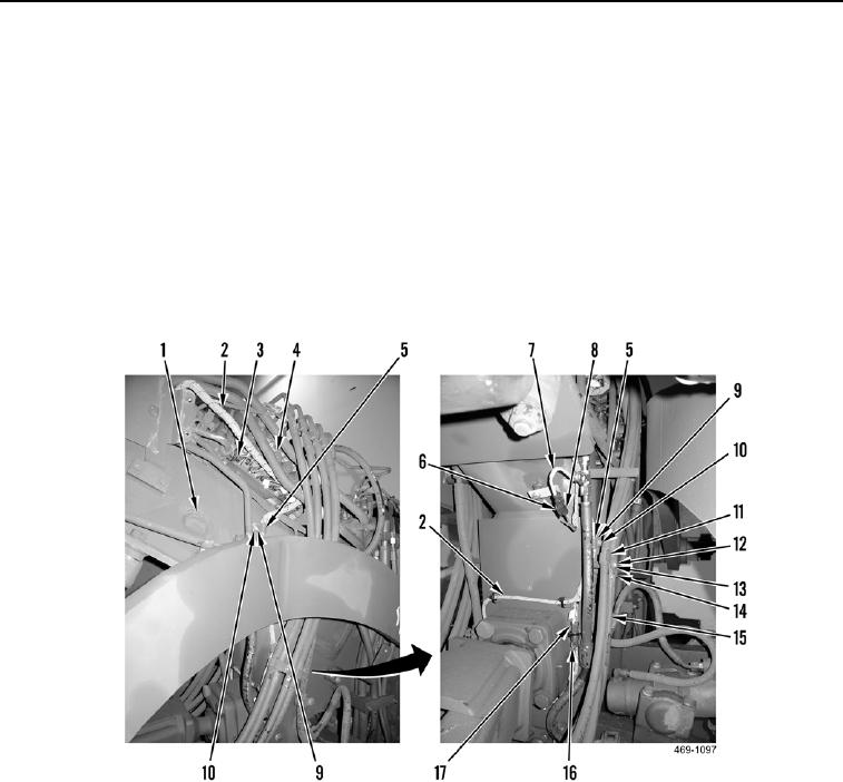
4. Remove bolt (Figure 2, Item 12), washer (Figure 2, Item 13), spacer (Figure 2, Item 14) and two plates
(Figure 2, Item 11) from hoses (Figure 2, Item 15). Position hoses aside.
5. Disconnect front attachment wiring harness connector (Figure 2, Item 17) from steering cylinder connector
(Figure 2, Item 16).
6. Disconnect steering oil temperature sensor (Figure 2, Item 7) from front attachment wiring harness connector
(Figure 2, Item 8).
7. Remove front attachment wiring harness connector (Figure 2, Item 8) from clip (Figure 2, Item 6).
8. Remove two bolts (Figure 2, Item 10), washers (Figure 2, Item 9), and clamps (Figure 2, Item 5) from front
attachment wiring harness (Figure 2, Item 2) and front frame (Figure 2, Item 1).
9. Disconnect six front attachment wiring harness connectors (Figure 2, Item 3) from front frame valve bank
(Figure 2, Item 4).
Figure 2. Right Front Frame Valve Bank Connections.
0180

