
TM 5-3805-293-23-3
0166
INSTALLATION
000166
N OT E
Install wires as noted during removal.
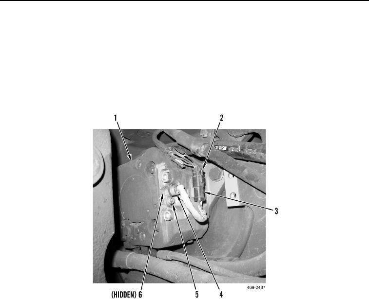
1. Install O-ring (Figure 3, Item 6), front drive motor speed sensor (Figure 3, Item 4) and bolt (Figure 3, Item 5) on
all-wheel drive motor (Figure 3, Item 1).
2. Connect electrical connector (Figure 3, Item 3) to all-wheel drive wiring harness (Figure 3, Item 2) and install
electrical connector (Figure 3, Item 3) on all-wheel drive motor (Figure 3, Item 1).
Figure 3. Speed Sensor
0166
Change 1